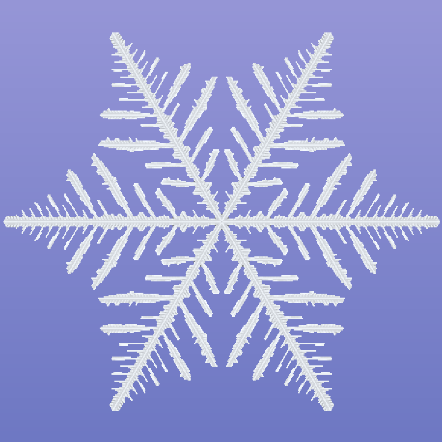
I Stopped Drawing Snowflakes and Started Growing Them
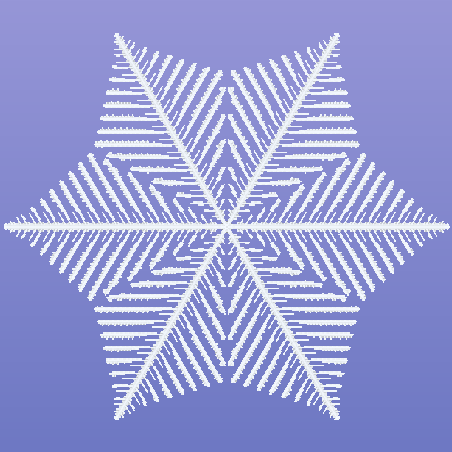
Building a cellular-automata snow crystal generator in Houdini
<!-- HERO: Final Karma render, cropped square. If possible, use a frame with visible internal relief and edge sparkle rather than a flat silhouette. -->There is a fast way to make a procedural snowflake: draw one branch, rotate it six times, and add enough noise that the repetition is not immediately obvious.
I tried that first. It works—but it still feels like a symbol of a snowflake rather than a crystal that formed.
For this Houdini project, I wanted the branching, plates, ridges, and final silhouette to come from a growth process. I also wanted the result to remain practical for production: art-directable controls, deterministic seeds, animatable formation, a watertight mesh, and a render setup that made nearly transparent ice readable.
The final tool combines a NumPy cellular automaton inside a Python SOP with VEX-based geometry processing, VDB meshing, and a MaterialX/Karma look-dev setup. The important shift was simple: instead of procedurally drawing a snowflake, I let a simulated crystal decide where the geometry should exist.
The versions that led to the final system
The project went through several approaches before arriving at the cellular automaton.
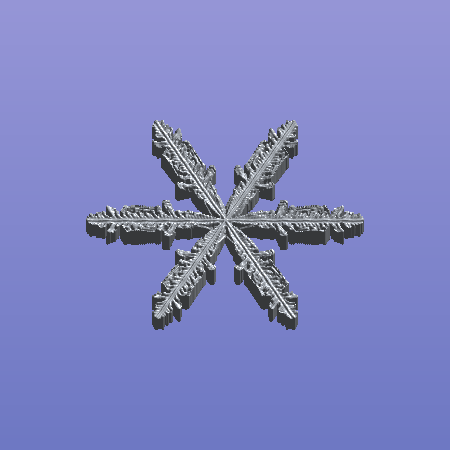
The first version generated a single template arm in VEX. It placed points along a spine, added seeded side branches and sub-branches, mirrored the result, and rotated it around the center. A normalized buildorder attribute made it possible to reveal the points from the center outward.
That system gradually became more sophisticated:
| Version | Main idea | What it solved |
|---|---|---|
| v1 | Seeded particle branches | Fast, controllable snowflake silhouettes and animated growth |
| v2 | Structural groups and metadata | Separate control of spines, branches, plates, twins, and rime |
| v3 | An implicit solid filled with a crystal lattice | Resolution-independent silhouettes and real thickness |
| v4 | Separate skeleton, lattice, and multithreaded carve stages | Better performance and cleaner responsibilities |
| v5 | Exact segment and polygon SDFs written directly to VDBs | Removed scalloping from point-sampled surfaces |
| v6 | Connected splines with a custom faceted sweep | Clean low-poly blades, slabs, rims, and center ridges |
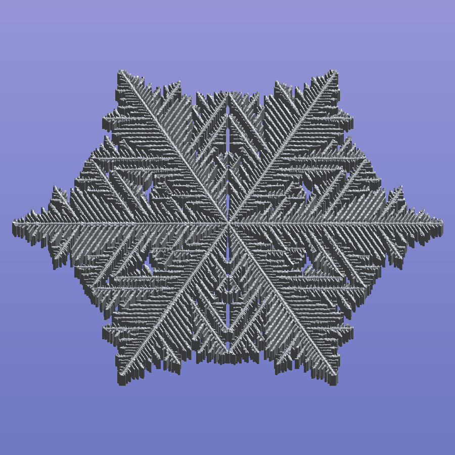 |
Each version solved a meshing or representation problem, but the underlying branch structure was still authored by rules: place a branch here, taper it there, copy it around the center.
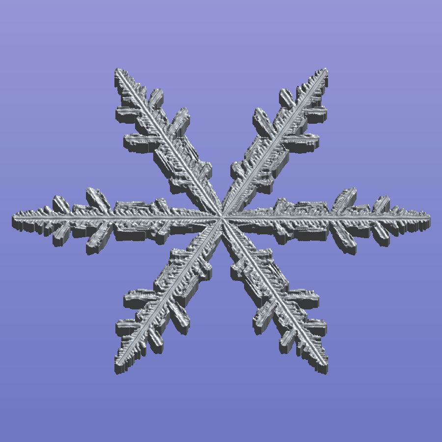
The final version changed the source of the shape itself. A growth simulation now decides which lattice cells become ice. Houdini takes over only after that decision has been made.
A snowflake is a process, not a pattern
The sixfold structure of a snow crystal ultimately comes from the hexagonal arrangement of molecules in the ice lattice. Its larger form emerges through a mix of faceting, vapor diffusion, attachment, and instability at the growing boundary. Kenneth Libbrecht gives an excellent visual explanation in Snowflake Science.
My simulation is based on the mesoscopic lattice model described by Janko Gravner and David Griffeath in Modeling Snow Crystal Growth II. Their model combines diffusion-limited growth, anisotropic attachment kinetics, and an idealized quasi-liquid boundary layer. It is not a molecular simulation, but it captures a surprisingly wide family of faceted and dendritic planar forms.
The automaton runs on a triangular lattice, which means every cell has six neighbors. Each cell stores four main pieces of state:
| State | Meaning in the model | How I use it |
|---|---|---|
a | Whether the cell has attached to the crystal | Defines the final snowflake footprint |
b | Quasi-liquid mass on the boundary | Participates in attachment and melting |
c | Frozen crystal mass | Drives the final surface relief and ridges |
d | Diffusive vapor mass | Supplies new material to the growing crystal |
Every simulation step has four phases:
- Diffusion averages vapor across each cell and its six neighbors. Attached cells act as reflective boundaries rather than vapor reservoirs.
- Freezing moves vapor at the crystal boundary into quasi-liquid and solid crystal mass.
- Attachment decides whether a boundary cell becomes part of the crystal. The threshold changes according to how many neighboring cells are already attached.
- Melting returns some mass from boundary cells that did not attach back into the vapor field.
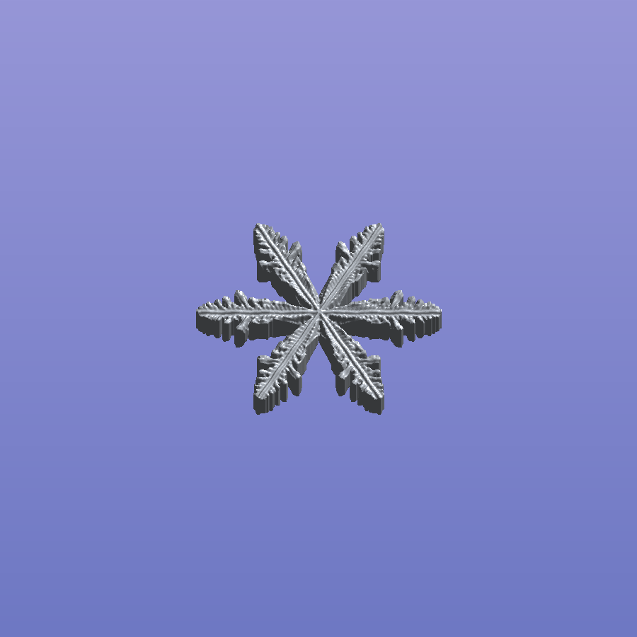
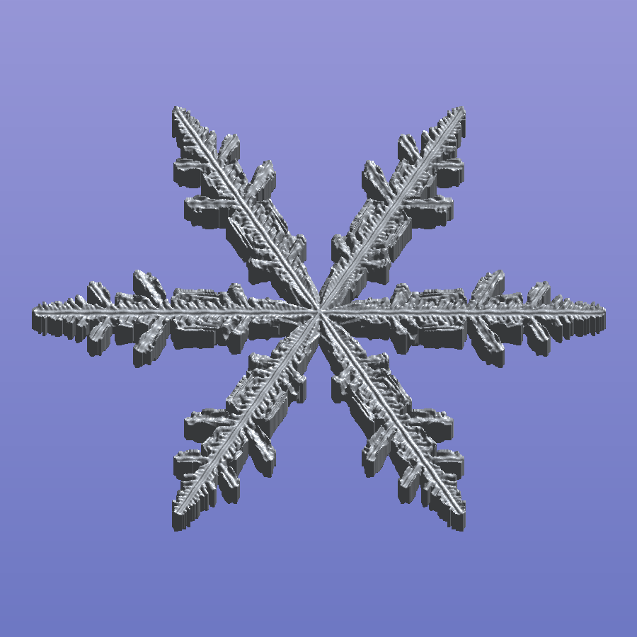
A single attached cell at the center is enough to start the process. From there, the competition for vapor naturally amplifies corners and tips. Small differences become branches; branches shield nearby regions from vapor; new instabilities form on the branches. The complexity is an outcome of local rules rather than an explicitly drawn hierarchy.
Turning scientific parameters into artist controls
The original model exposes parameters with names such as rho, beta, alpha, theta, kappa, mu, and gamma. Those are useful when studying the system, but they are not the controls I want to reach for while designing a shot.
I mapped them to a smaller set of perceptual controls:
| Control | What it changes |
|---|---|
| Branchiness | Raises the vapor supply, makes tip attachment easier, and sharpens the boundary through additional melting. Low values favor compact plates; high values produce open dendrites. |
| Plate Fill | Changes how readily concave, three-neighbor regions attach, filling space between branches into broader plates and sectors. |
| Detail | Adjusts the exchange between boundary mass, frozen crystal mass, and melting, changing the amount of fine internal structure available for relief. |
| Irregularity | Adds seeded variation to the initial vapor field. The result remains deterministic for a given seed. |
| Lattice Radius | Controls the simulation resolution at a fixed final flake size. |
| Max Growth Steps | Limits how long the automaton is allowed to evolve before it reaches the edge of the domain. |
The tool includes presets for Stellar Dendrite, Fernlike Dendrite, Sectored Plate, and Simple Plate. These are starting points rather than locked species. The useful results usually live between them.
There is also a draft mode that halves the lattice radius and step budget while using a coarser VDB. That made it possible to explore seeds and broad morphology quickly, then switch to full quality for the final mesh.
Simulating only one-twelfth of the flake
A full hexagonal domain contains a great deal of redundant work if the target is an iconic, symmetric snowflake. I simulate only a 30-degree wedge.
Neighbors that cross either side of the wedge are folded back through the symmetry operations of the hexagonal lattice. This creates exact reflective boundaries during the simulation—not a mirror operation applied after growth. Once the simulation is complete, the wedge is mirrored and copied six times in SOPs to reconstruct the full crystal.
At a lattice radius of 200, the full hexagonal domain would contain 120,601 sites. The canonical wedge contains only 10,201. That reduction is what makes the NumPy implementation comfortable inside an interactive Houdini tool.
There is a second optimization inside the loop. The lattice is stored ring by ring, and each step touches only the active prefix close to the advancing crystal. Regions beyond that front still contain uniform vapor, so updating them would not change anything.
This symmetry is a deliberate creative choice. Real snow-crystal arms grow independently under similar environmental conditions, and most natural crystals are less perfect than the specimens photographers tend to select. Here, exact symmetry gives me the graphic clarity I want and a major performance win. The Irregularity control breaks up the growth inside the wedge, but that variation is repeated around the flake.
<!-- IMAGE 4: Diagram or viewport capture showing the simulated 30-degree wedge, the mirrored 60-degree sector, and the six rotated copies. -->Growth animation without re-simulating
When a cell attaches, the simulation records the step in t_attach. That gives me a complete growth history in one cook.
The animation stage is then just a point filter:
float frac = chf("../growfrac_eff");
if (frac < 1.0)
{
    float steps = detail(0, "steps");
    if (f@t_attach > frac * steps)
        removepoint(0, @ptnum);
}
Animating Growth from 0 to 1 replays the actual attachment order. It does not invent a radial wipe, and it does not need to run the automaton again on every frame. Branches emerge when they emerged in the simulation, while plate regions fill according to their own local history.
For heavier look development, a Stash SOP freezes the simulation result. I can then adjust thickness, relief, VDB resolution, materials, lights, and the growth animation without touching the expensive stage upstream.
Converting cells into a renderable crystal
The simulation outputs points, but I wanted a faceted, watertight object with meaningful thickness—not a cloud of spheres.
The SOP pipeline is:
- Output attached lattice cells. The Python SOP creates a point for each attached cell and transfers
massandt_attach. - Replay growth. A VEX filter removes cells that have not attached by the current growth fraction.
- Unfold the wedge. A Mirror SOP creates a 60-degree sector, and Copy and Transform repeats it six times. Fuse removes duplicates on the seams.
- Build the plate. Each lattice point becomes its hexagonal Voronoi tile. Fusing the tile corners creates a connected, lattice-aligned surface while preserving the stepped crystalline silhouette.
- Create surface relief. A point-cloud lookup samples nearby crystal mass. The normalized and gamma-shaped mass becomes a half-thickness value, with optional attachment-time bands for subtle growth rings.
- Make it solid. PolyExtrude creates both caps, and a VEX pass moves them to
+hhand-hh, giving the basal faces symmetric relief. - Polish with VDBs. VDB From Polygons, a small SDF smooth, and Convert VDB close the result into a watertight mesh and soften the most digital edges without erasing the lattice character.
- Finish the normals. Point normals with a controlled cusp preserve readable facets while allowing the shallow relief to catch light smoothly.
One of my favorite parts of the setup is that the visible relief is not a generic noise displacement. It comes from the crystal mass accumulated during growth. The form and the surface detail therefore share the same history.
<!-- IMAGE 5: Horizontal pipeline strip: lattice points → hex tiles → relief plate → solid mesh → VDB-polished result. Use the same seed and framing. -->Making transparent ice visible
Clear ice can disappear quickly in a conventional studio setup. A white object on a white background is easy; a nearly transparent object whose important details are shallow refractions is not.
I built the final look in Solaris with a MaterialX Standard Surface shader:
- Base weight: 0
- Specular: 1
- Specular roughness: 0.03
- Specular IOR: 1.31
- Transmission: 1
- Thin-walled: off, because the generator creates real thickness
The key to the render is an emissive lightbox card placed below the flake. Its pale lavender-to-blue gradient is both the visible background and the information the crystal refracts. When the sloped relief bends a ray, that ray lands on a different part of the gradient, revealing structure that would vanish against a flat color.
A broad top light adds soft specular glints, a low grazing light catches the branch tips and faceted rim, and a subtle cool dome keeps the front faces from going dead. The camera looks straight down, echoing snow-crystal photomicrography.
For the supplied Karma setup, I used a square 1080 render, 64 samples per pixel, a refraction limit of 8, and a reflection limit of 6. Those settings are intentionally conservative enough for the layered transmission while remaining practical for look development.
<!-- IMAGE 6: Lighting breakdown with beauty, lightbox only, top key only, and rim only. -->What I learned
The most important lesson was that representation and formation are separate problems.
Particles, VDBs, splines, and polygon sweeps can all make excellent snowflake geometry. I built working versions with each of them. But changing the meshing method did not automatically make the structure feel grown. That only happened when the growth process became responsible for the silhouette.
The cellular automaton also created a useful chain of causality:
- Vapor and attachment rules determine the footprint.
- Attachment time determines the animation.
- Accumulated crystal mass determines the surface relief.
- The relief determines how the light refracts through the final ice.
That continuity is what makes the generator feel coherent. The final render is not a procedural outline with unrelated detail added afterward. Its shape, animation, surface, and shading all trace back to the same simulated history.
There is still plenty I would like to explore. The current tool holds its environmental controls constant during a simulation; animating those conditions over growth time could produce more dramatic transitions between plates and dendrites. I would also like an optional asymmetry stage that introduces small per-arm changes after unfolding while preserving the underlying sixfold structure.
For now, though, this project gave me what I was after: a snowflake generator that behaves less like a drawing tool and more like a small crystal-growing machine.
References
- Janko Gravner and David Griffeath, Modeling Snow Crystal Growth II: A Mesoscopic Lattice Map with Plausible Dynamics, Physica D 237 (2008), 385–404. DOI
- Kenneth G. Libbrecht, Snowflake Science